Autonomous Lawnmower - Sensor Setup and Integration
This report details the sensor selection, setup, and integration process for developing an autonomous lawnmower capable of reliable obstacle avoidance and precise navigation in challenging outdoor environments.
3. Demonstration
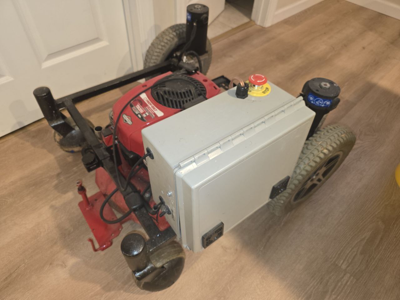
Figure: Demonstration of the autonomous lawnmower controlled via a smartphone.
4. Structure
The autonomous lawnmower is composed of a mechanical base integrated with a robust electronic control system. The components work together to ensure reliable navigation, obstacle avoidance, and remote operation.
Component Layout
The main elements of the lawnmower system are strategically placed:
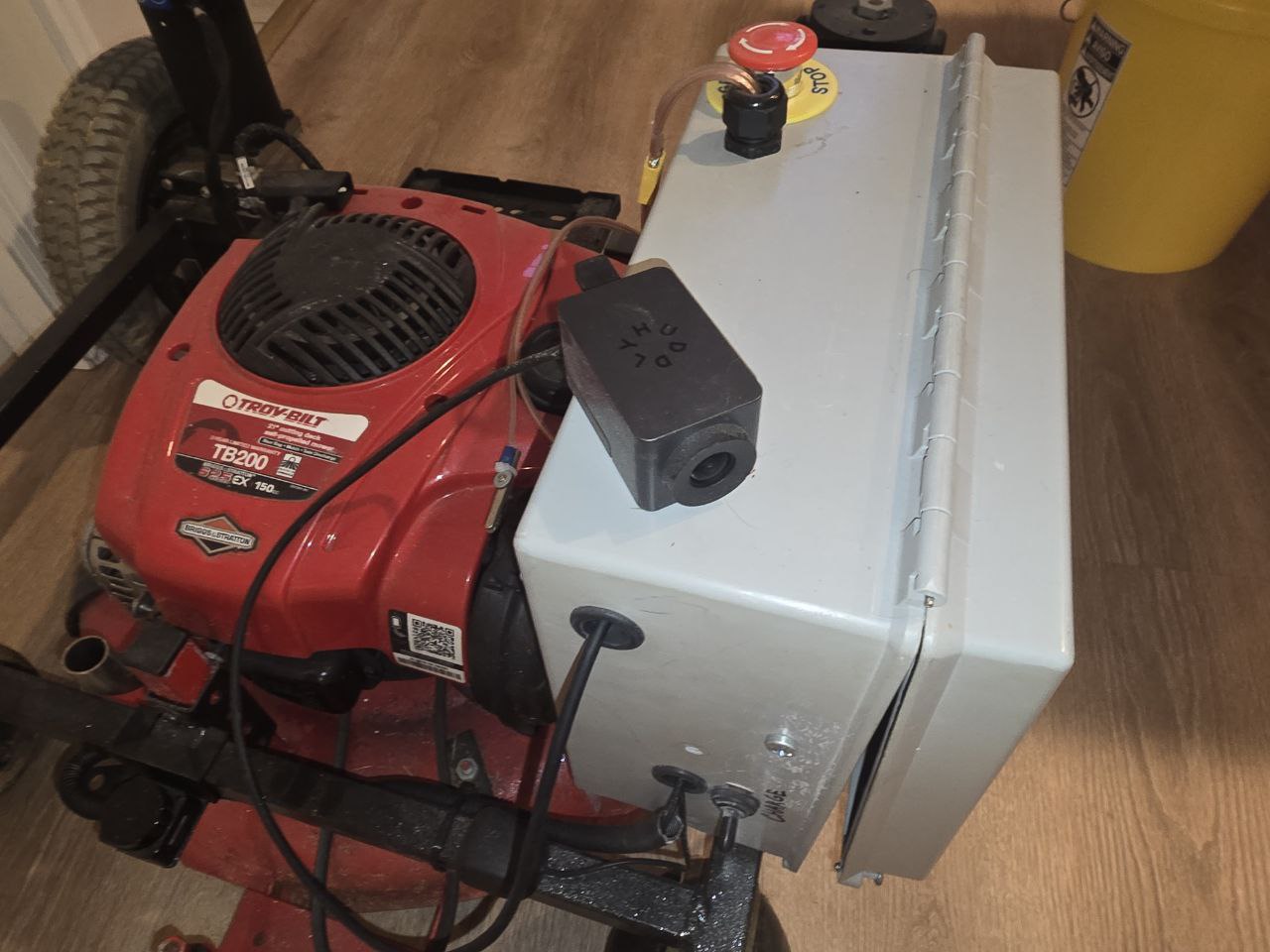
Mechanical Base: The red Troy-Bilt TB200 engine provides the primary power for propulsion and mowing. It serves as the foundation of the system.
Electronics Enclosure: Positioned on top of the engine, the gray box houses critical electronic components, including controllers, relays, and a charge management system.
Emergency Stop Button: Mounted on the gray enclosure, this safety feature allows for an immediate shutdown in case of emergency.
Computational Unit: Inside the enclosure, the iuniker Raspberry Pi Case with a dual-fan cooling system houses a Raspberry Pi 3 Model B for data processing and control of navigation and obstacle avoidance.
Cooling Fans: Located on the sides of the gray enclosure, they ensure proper ventilation to prevent overheating of internal components.
Sensors: The setup includes ultrasonic sensors and other peripherals for obstacle detection, mounted at the front and rear for comprehensive coverage.
Camera: A Huddly Go 1.0 high-end conferencing camera is included for video monitoring and advanced navigation capabilities.
Figure 1: Exterior View of the Lawnmower
This figure shows the overall design of the autonomous lawnmower. The red base houses the Troy-Bilt TB200 engine, which provides the mechanical power for cutting or propulsion. The gray enclosure on top contains the electronic components for automation and control. Additionally, the Huddly Go Camera enhances visual monitoring and navigation capabilities.
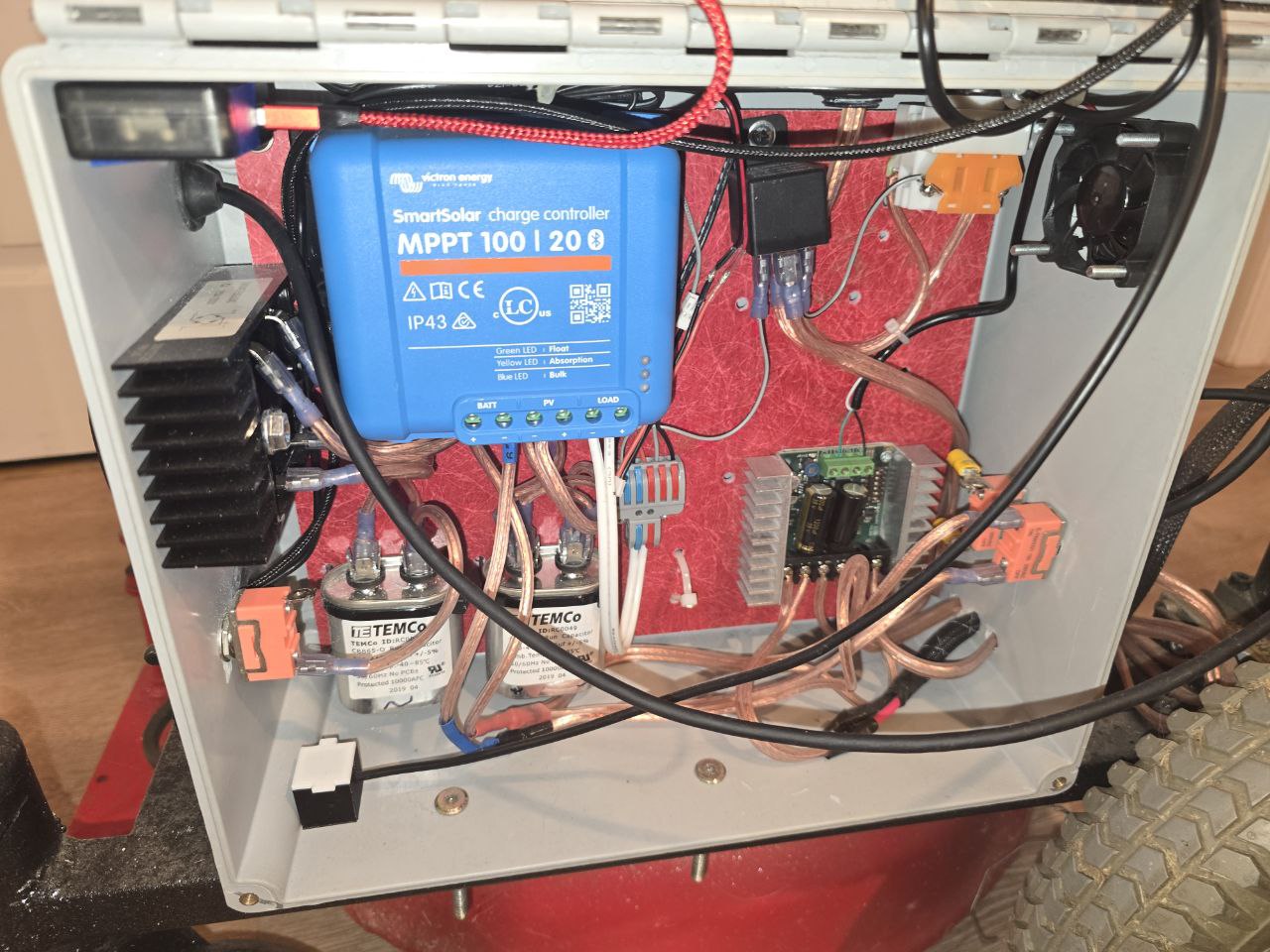
Figure 2: Interior of the Electronics Enclosure
This figure provides a closer look at the components inside the gray electronics enclosure. Key elements include:
SmartSolar Charge Controller: Manages the battery charging process, optimizing energy intake from solar panels.
TEMCo Relays: High-current switches to control power flow to motors or other components.
Cooling Fan: Prevents overheating of internal components.
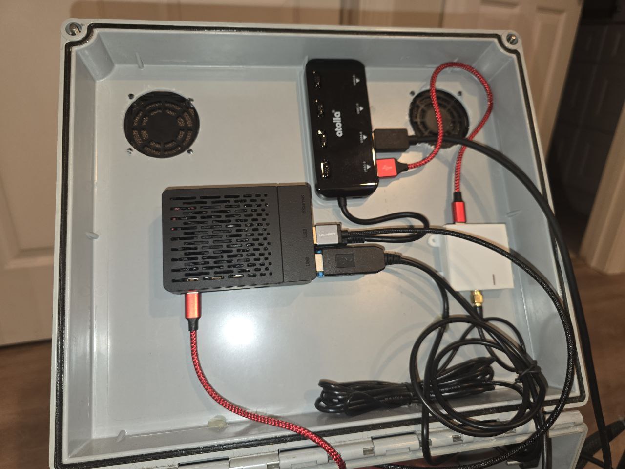
Raspberry Pi Case: The iuniker Raspberry Pi Case with dual fans protects the Raspberry Pi 3 Model B while ensuring optimal cooling.
USB Hub: The Atolla 4-Port USB 3.0 Hub connects peripherals such as sensors and communication devices.
Wiring: Distributes power and control signals between components.
5.1 Sensor Selection and Rationale
The obstacle avoidance system for the autonomous lawnmower was designed to operate reliably in outdoor environments characterized by high vibrations, humidity, and exposure to grass clippings. Initial evaluations of sensor technologies included:
Ultrasonic Sensors: The widely used HCS4 ultrasonic sensor was deemed unsuitable due to its susceptibility to environmental factors such as grass clippings entering the transducers and rendering them inoperative.
LiDAR Sensors: Compact laser sensors like the TF Mini LiDAR, though precise, offered a limited field of view, making them impractical for comprehensive coverage.
As an alternative, automotive parking sensors were selected for their robustness, affordability, and compatibility with custom interfacing solutions. A commercially available eight-sensor parking module was used, capable of detecting obstacles with centimeter-level precision. This decision leveraged the module's built-in signal processing and real-world reliability in adverse conditions.
5.2 Parking Sensor Module Integration
5.2.1 Hardware Setup
The eight-sensor module included:
Ultrasonic Sensors: Mounted at the front and rear of the lawnmower, replicating typical car installations.
Control Unit: Responsible for generating and processing sensor signals.
Output Display Module: Used for debugging during initial setup.
Sensors were mounted in 3D-printed enclosures attached to the lawnmower's front bumper. These housings were designed to shield sensors from environmental hazards while maintaining optimal field of view.
5.2.2 Signal Decoding
Data from the sensor module was accessed via a logic analyzer to understand its communication protocol. Observations included:
Packet Structure: Each data packet began with a 1ms starting pulse, followed by a sequence of shorter pulses representing binary data. These binary sequences encoded both the sensor address and the measured distance.
Timing Characteristics: Packets were transmitted every 35ms, ensuring low latency for real-time obstacle detection.
5.2.3 Microcontroller Interfacing
The parking sensor module was interfaced with an Arduino Due microcontroller:
Signal Pin Connection: The signal wire from the sensor control unit was connected to pin 7 on the Arduino.
Data Processing: A 32-bit unsigned integer was used to store complete data packets, with 8 bits allocated for the sensor address and 8 bits for distance values.
Pulse Measurement Logic: The Arduino sketch included logic to detect starting pulses and map subsequent pulses to binary data. Decoded values were printed via the serial port for debugging.
5.2.4 Results from Signal Decoding
Initial tests revealed an issue: although the module supported eight sensors, only six were actively transmitting data packets. Investigation showed that the middle two front sensors were inactive, likely due to a limitation in the module's firmware. This anomaly was deemed acceptable, as the application prioritized precision over coverage.
5.3 GPS Real-Time Kinematics (RTK) Integration
5.3.1 RTK Setup
To enable precise navigation, the project employed RTK technology using the ZED-F9P GPS module. The RTK system provided centimeter-level accuracy by correcting positional data using a base station. Key steps included:
This udev rule allows the GPS to be initialized when plugged in and starts the corresponding service automatically. The service file should be placed in /etc/systemd/system/location@.service with the following content:
[Unit]
Description=RTCM Base Station

[Service]
ExecStart=/usr/local/bin/str2str -in serial://ttyACM0:115200:8:n:1:off -out ntrips://:6n9c2TxqKwuc@rtk2go.com:2101/Wexford
Restart=always
User=nobody
RestartSec=1 # Restart after 1 second

[Install]
WantedBy=multi-user.target
After creating the service file, enable and start the service:
The live stream will be accessible at 192.168.0.127:3000.
5.5 Challenges and Solutions
5.5.1 Sensor Reliability
Signal inconsistencies were observed during early tests, likely caused by environmental noise. These were mitigated by:
Adding capacitors to stabilize power supply lines.
Implementing software-based noise filtering.
5.5.2 GPS Drift
GPS drift under dense foliage and during overcast conditions was addressed by:
Optimizing base station placement for unobstructed sky visibility.
Adjusting RTKLIB settings to prioritize accuracy over update rate.
5.5.3 Sensor Coverage
The inability of the middle front sensors to detect obstacles was attributed to module limitations. Alternative placement and reliance on active sensors ensured adequate coverage.
6. GPS-Rider and GPS-Station Integration
6.1 GPS-Rider Setup
The GPS-Rider repository handles the real-time streaming of GPS data to the autonomous lawnmower. Key configurations include:
Running network services on 192.168.0.127:3000.
Installing and configuring RTKLIB as detailed above.
Managing device connections using systemd and udev rules.
udevadm monitor
udevadm info -a -n /dev/ttyACM0 | less
Test the port using screen:
screen /dev/ttyACM0 115200
Ctrl-a+Ctrl-\ - Exit screen and terminate all programs in this screen.
Ctrl-a+d or Ctrl-a+Ctrl-d - "minimize" screen, screen -r to restore it.
6.2 GPS-Station Setup
The GPS-Station repository manages the base station operations for RTK corrections. Steps include:
Registering and configuring the RTK2go caster with the provided mount point and password.
Example service file content:
[Unit]
Description=RTCM Base Station

[Service]
ExecStart=/usr/local/bin/str2str -in serial://ttyACM0:115200:8:n:1:off -out ntrips://:6n9c2TxqKwuc@rtk2go.com:2101/Wexford
Restart=always
User=nobody
RestartSec=1 # Restart after 1 second

[Install]
WantedBy=multi-user.target