Autonomous Cube-Tower Construction (Franka Panda)
Demonstration
On-site clip: about the first three minutes of the lab recording at 3× speed (~60s playback), orientation corrected. Full recordings: PEARL Nextcloud (original capture) · Google Drive (report supplement)
Interactive rosbag / perception debug viewer (50 real rosbags: masks, poses, fused top-down view)
PEARL Lab — Perception, Reasoning, and Learning
Introduction
The task is to build a vertical tower from identical cubes on a flat table. Two RGB-D cameras cover opposite corners: one on the right facing the robot, one at the back-left. The Franka Emika Panda sits centered on the back edge. The pipeline supports variable cube counts; our main experiment targets a five-cube tower.
Perception
We use a multi-stage RGB-D pipeline: table detection and calibration, dual-camera acquisition, SAM3-based cube segmentation, mask filtering, then multi-view pose estimation and fusion. The table is found first with SAM3 text prompts; we derive a table mask, filled footprint, and a keep region reused for all later cube detections. That isolates the workspace, reduces background noise, and avoids interference from white tape on the real table.
Each camera is processed independently, then fused. One sensor was less reliable far from its viewpoint, so we treat detections as proposals, match poses across views by geometric compatibility, and let the more reliable view anchor each fused cube.
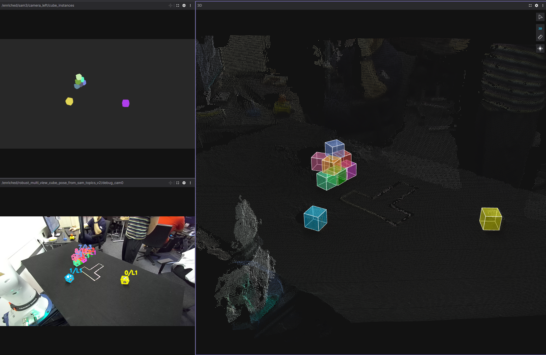
Cube masks come from SAM3 on the cropped table region. Raw masks are only proposals: we filter by footprint, size, and overlap; merge and split with connected components and geometric cleanup; use depth lightly for consistency. For each valid mask we back-project depth to 3D, estimate a shared table plane in the robot frame, infer layer height and yaw, and reconstruct the 3D center using the known cube size.
Figure: multi-view recovery
Control and planning
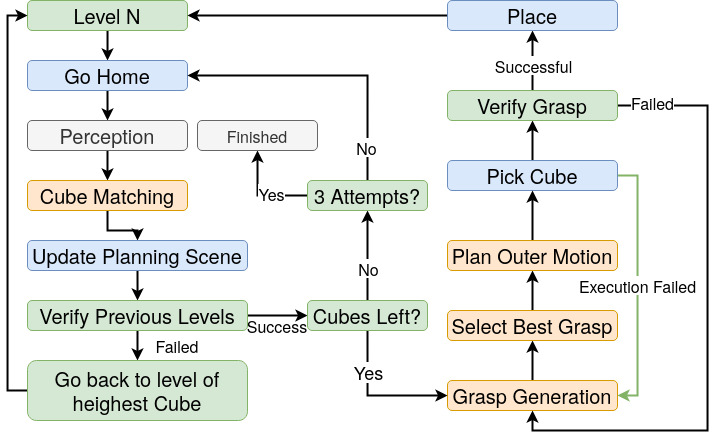
Planning and execution run on MoveIt: collision checking, trajectories, and a planning scene updated from perception. Modules include Cube Matching (scene ↔ detections), Build Site Planner (Gaussian-sampled tower placement with reachability, collision, proximity, and workspace-centered scoring), Grasp Generation (parallel ROS workers, 12 grasp hypotheses per cube before filtering, paired place candidates, ranked and coordinated), Control (retimed trajectories, pick-place with force-controlled grasp and scene attach/detach), and a Task Planner based on a behavior tree with scan–verify–manipulate loops and recovery when the tower or grasps fail.
Figure: behavior tree (high level)
Results
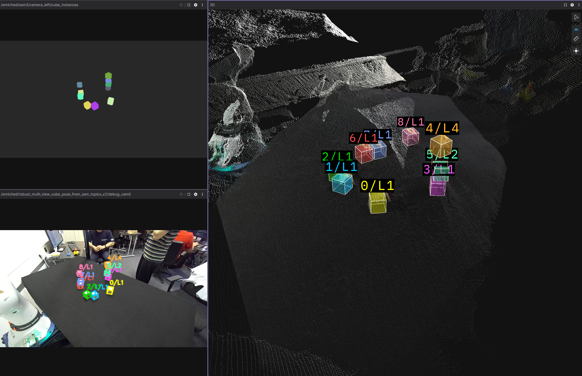
The integrated system builds the tower from random initial layouts using only perception, and recovers from several failures (removed or fallen cubes, failed grasps, last-second cube removal). Remaining issues include rare duplicate cubes in the planning scene blocking grasps, and occasional wrong layer assignment leading to risky rebuild attempts—often mitigated by the task planner if the scene stays recoverable.
Figure: successful perception
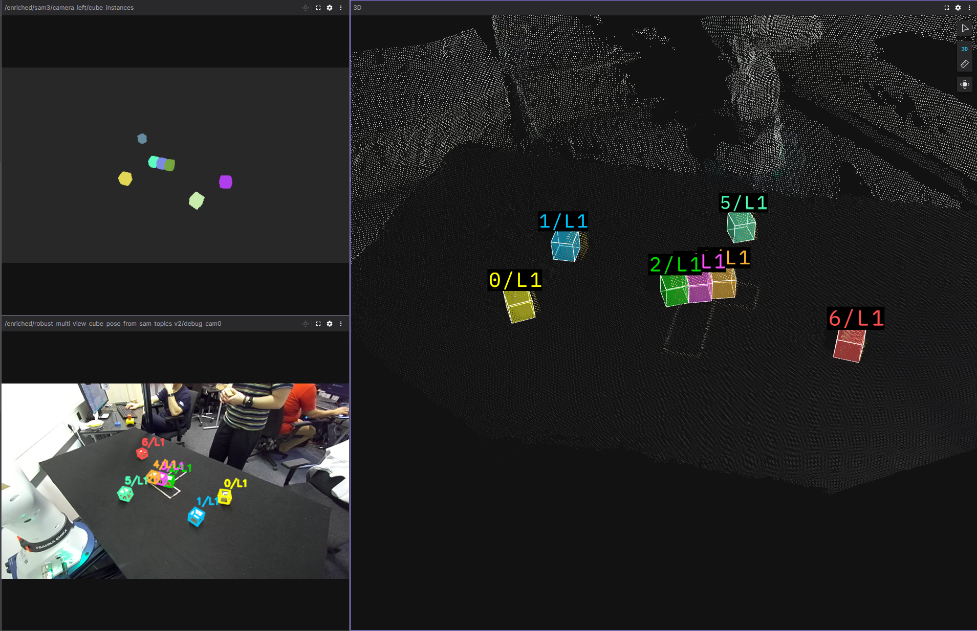
Figure: difficult case (layer inconsistency)
Perception was developed against 50 real rosbags; the debug viewer links each bag to saved masks, overlays, and fused views for structured failure analysis.
Limitations (summary)
- Perception runs with the arm out of view — motion and sensing are serialized.
- Task logic is specialized to vertical towers; other geometries need re-engineering.
- Grasping assumes cubes on the table plane; cluttered stacks or deconstruction are out of scope.
- Segmentation and cleanup still depend on tuned thresholds when lighting or scenes change.
- Lower tower layers are harder under occlusion; layer hallucinations or misses can confuse matching.
- Towers near the table edge can be clipped by the table mask — center placements are safer.
img/ folder (example_result.png, simple_result.png, missing_layer.png, BT.jpeg).